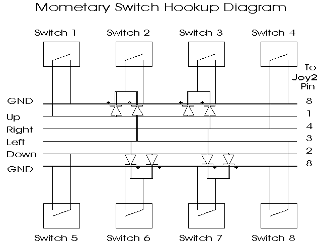
After finalizing the computer we would be using and finishing the system outline, we began selecting and interfacing the component parts to it. The first hardware task was interfacing the client input. We hooked the arcade buttons in a four-by-two matrix, the configuration the client was familiar with (see Figure 6 in Software Section). Then, we connected the switches to four of the joystick inputs on the computer in an eight position "direction" simulation, as shown in Figure 2. The switches we used were all from arcade games and the diodes were standard geranium diodes.
Figure 2: Arcade Button Wiring Diagram

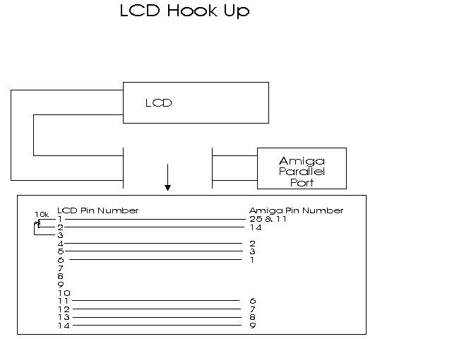
The next step was to interface the client feedback device, the LCD. This proved more difficult, and in the process of attempting to interface the LCD’s several were destroyed. The LCD we selected was an intelligent 4/8 bit data, 40 character by 2 line display. It needs an additional one to three control data bits depending on the application; for our application it needed one additional data bit giving us a net need of five or nine data bits. We decided to use the 4 bit option because we would be hooking the LCD’s to an 8 bit interface. We found the timing control line to correspond to the STROBE line on the 8 bit interface. From this, after some more trial and tribulation, we came up with an easy way to interface these displays to the Amiga 600, shown in Figure 3. The 10k pot on the LCD side adjusts the center of the viewing angle.
Figure 3: LCD to Amiga Parallel Port Wiring Diagram

The next step was to build an audio amplifier. After much experimenting we found that a $12 amp from Radio Shack™ worked as well as those amps with wiring diagrams in The Engineers Mini-Notebook series[FM87]; this was due to an oversight in the schematics which we later solved by putting in a matching transformer going to the speaker. With that modification the sound quality was well above that of the $12 amp, but before implementing this into a system we found another, better, solution. Slight modification of a $20 computer speaker system resulted in very high quality output and this modified system has become the standard for future models. Unfortunately we found these improvements after the initial device was sent to the client, but these changes will be kept in mind for all future models.
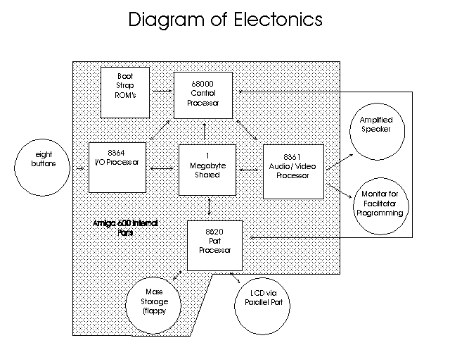
With the completion of the speaker system, our core computer system was finished. It has input in the form of buttons, output in the form of sound, and processing facilities suitable for our client. The computer was set up in a convenient, friendly environment for us to write the software in. A simplified diagram of the main parts is shown in Figure 4.
Figure 4: Simplified Diagram of Project Hardware

This configuration gives us many useful characteristics, especially in helping ensure real-time responses. It has four processors that we will be taking advantage of, the 68000 CPU, the 8364 I/O processor, the 8361 A/V processor, and the 8620 port processor. The 8364 processor handles the client button input in a buffered fashion; so the client can continue using the buttons while the system is performing other functions (like speaking). The 8361 processor in very useful because, once activated, it will generate the sound and video without CPU overhead (the machine can be processing information while speaking). The 8620 processor allows file I/O and LCD output to be taking place without CPU overhead; allowing the system to continue processing while files are being loaded and saved, or when LCD output is being displayed. This multi-processor environment gives us good resources for the real-time applications of spontaneous conversation.
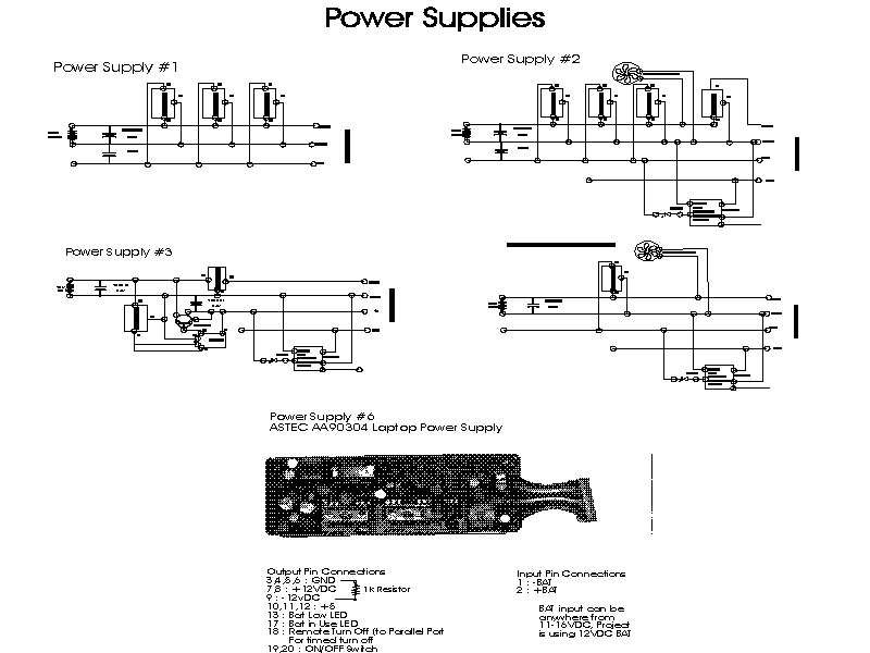
Figure 5: Power Supplies

The last challenge was the power supply. We decided that 12VDC would be the most convenient battery source. The commercial applications in camcorders, motorcycles, and cars make this the cheapest power source by far. According to early research, the only absolutely necessary voltages are +12,+5, and Ground. This is reflected in Power Supply #1 as show in Figure 5. Power Supply #1 is a modification of a circuit for use with logic IC’s published in Engineers Mini-Notebooks [FM87]. It worked quite well with the exception that there was a considerable amount of noise coming out of the audio channels. We found this to be caused by the need of the additional voltage of -12VDC. There were many variations tried, including the five major power supplies version shown in Figure 5. After we shipped the aide with Power Supply #4 to Michael we found the better alternative of a surplus laptop power supply. This is Power Supply #5 in Figure 5, it performed magnificently and we will use it in all future models. A comparison of the various power supplies shown in Table 1 is provided for an empirical comparison.
Table 1: Power Supply Comparison
The Power Supply Number |
Minimum Efficiency |
Cost |
Time to build/incorporate |
1 |
45% |
$6 |
60 mins |
2 |
40% |
$25 |
75 mins |
3 |
50% |
$12 |
75 mins |
4 |
40% |
$23 |
45 mins |
5 |
80% |
$15 |
30 mins |
For calculating battery life, the complete machine draws 13 watts, or 1.1 amps at 12VDC, which gives the formula in Equation 1.
Equation 1: Formula For Calculating Battery Life
![]()
So at 100% efficiency with the 2.4 amp hour camcorder battery, the aide would give approximately 130 minutes of use.
The final step, in the hardware category, was the input provision for speech. The project uses digitized speech samples to guarantee a natural sounding voice. We accomplished this by using an audio digitizer designed to work with the Amiga computer and a lapel microphone. With this set up a voice saying a list of common words only needed to be digitized once, and it was then stored on disk for playback by the software. For more information about digitized speech see Appendix A.
Previous Section Next Section Return To Thesis Home Return To Home Page